Problem 47-1
Source: 2ª question of 1º test - Electric Circuits - Ufrgs - 2017.
For the circuit shown in the Figura 47-01.1, calculate Io in function of
Vi.
Solution of the Problem 47-1
This circuit is composed of an operational amplifier (OP2) connected in the non-inverting configuration and another in the buffer configuration that feedback the output signal to the
non-inverter input of the OP2 . It is known that a buffer copies the signal on its input to the output without changing its phase and magnitude (gain = 1). Of the circuit, virtually
Va = Vb and, through a voltage divider can be written as:
Now using the nodal method for point a, we get:
After some algebraic manipulation in the above equation we obtain the following relation:
Substituting in this equation the value of Va found in eq. 47-01.1, we have:
However, from the circuit we can find a relation between Vo and
Vx.
Therefore, replacing this relation in the previous equation and after some algebraic manipulation, we get:
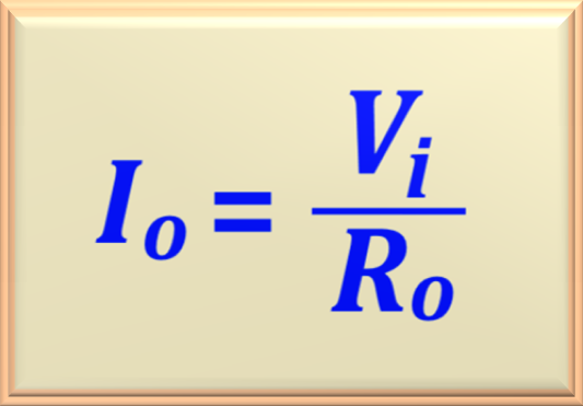
Note that if R1 = R2, the current Io
will only depend on the value of Ro (independent of the load). Therefore, this circuit behaves like a controlled current source by the input voltage Vi, that is: