Problem 43-1
Source: Problem 5-13 - page 179 -
ALEXANDER, Charles K., SADIKU, Mathew N. O. - Book: Fundamentos de Circuitos Elétricos - 5ª edição
- Ed. Mc Graw Hill - 2013.
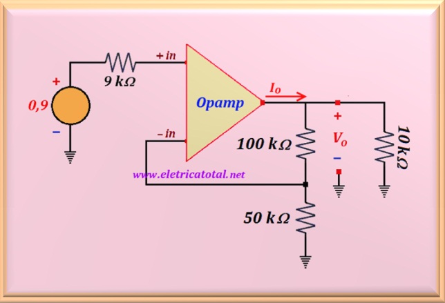
Determine Vo and Io in the circuit shown in Figura 43-01.1.
Figura 43-01.1
Solution of the Problem 43-1
Clearly this circuit is in the non-inverting configuration, because the signal is being
applied to the positive input. This means that the signal at the output of the operational amplifier
will be in phase with respect to the signal applied to the input. Notice that in this entry we have a
the resistive divider formed by the resistors of 10 kΩ and 90 kΩ.
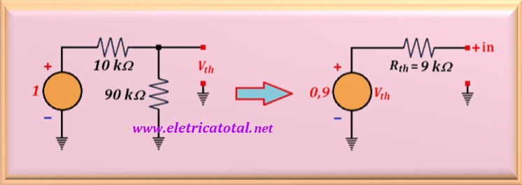
Then, the Thévenin equivalent is initially calculated for the input circuit.
Figura 43-01.2
On the left side of the Figura 43-01.2, the circuit is shown to calculate the voltage at
open circuit, which will be the voltage of Thévenin. The right side of the figure shows the circuit already transformed with its respective values.
How we found Vth = 0.9 volts ? Easy ... only solving a divider of
resistive voltage, that is:
Vth = (1 x 90) / (10 + 90) = 0.9 volts
And how we calculated Rth = 9 kΩ ? Now, simply apply a short circuit
in the voltage source, and with this, the two resistors remained in parallel. Solving the parallel
of the two resistors:
Rth = (10 x 90) / (10 + 90) = 9 kΩ
Now, the input circuit of the operational amplifier is replaced by the
Thévenin equivalent that was calculated. See in the Figura 43-01.3
for the circuit.
Figura 43-01.3
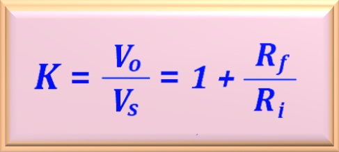
Recalling the eq. 43-01 that defines the gain in the non-inverting configuration of a closed-loop operational amplifier.
eq. 43-01
Assuming the operational amplifier as ideal, it is known that no electric current circulates in the inputs of the same. In this way, the which appears at the positive input is the same as the voltage source, ie 0.9 volts. Therefore, by applying the equation that determines the output voltage in the non-inverting configuration, we have:
Vo = K Vs = [1+(100/50)] Vs = 3 x 0.9 = 2.7 volts
We should calculate the electric current Io. Note, by the circuit, that
Io is the electric current that the operational amplifier provides to the output circuit,
which is formed by the resistors of 10 kΩ, 100 kΩ and 50 kΩ. In the case of the ideal
operational amplifier, there is no current flow in the
negative input. Then, the resistances of 100 kΩ and 50 kΩ act as load for the operational amplifier. This series set is in parallel with the
resistance of 10 kΩ. Then, by solving this parallel, we find of the load value for the operational amplifier.
RL = (10 x 150) / (10 + 150) = 9.375 kΩ
Therefore, the current Io is:
Io = Vo / RL = 2.7 / 9.375 = 0.288 mA = 288 µA
Note that when considering the operating amplifier as ideal, the calculations become quite simplified and straightforward.