Problem 41-1
Source: Problem adapted from the text on page 169 -
THOMAS, Roland E. , ROSA, Albert J. , THOUSSAINT, Gregory J. - Book:
The Analysis & Design of Linear Circuits
- 6ª Edição - Ed. John Willey & Sons, Inc. - 2009.
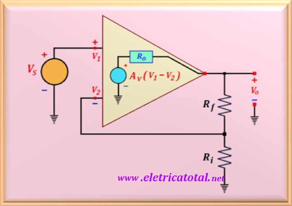
Assume that the operational amplifier in the circuit of the Figura 41-01.1 has an infinite input impedance and a voltage gain very large, but finite.
a) Determine the closed loop gain, Vo / Vs.
b) What is the effect of the feedback loop on the output impedance
Ro of the operational amplifier.
Figura 41-01.1
Solution of the Problem 41-1
Attention: The solution to this problem has been adapted from the existing text on page 167/168 of the book mentioned above.
Item a
For an ideal operational amplifier its voltage gain is considered as infinity. However, it is known that every real operating amplifier has a finite voltage gain. In this approach it was adopted that the amplifier operating voltage has a very large voltage gain but finite. As these devices currently have an input impedance of 106 or even
1012 ohms, it eliminated the input impedance in the circuit analysis.
Looking closely at the circuit you will notice that the voltage at the input
non-inverting is determined by the independent source Vs. For a very high input circuit impedance, this means that the current at the input is zero.
Then, to determine the voltage V2, in the invertor input, we used
a voltage divider with Ri and Rf, or:
V2 = Vo [Ri / (Ri + Rf )]
On the other hand, we can determineVo making a resistive divider with
Ro, Ri e Rf. And remembering that
V1 = Vs:
Vo = [(Ri + Rf ) /
(Ro + Ri + Rf )] [Av (Vs - V2 )]
Substituting the value of V2 found in the first equation in the latter and
after an algebraic arrangement in the expression, we get:
Vo = Vs [Av (Ri + Rf )] /
[Ro + Rf + Ri (1 + Av )]
Let's analyze this equation when we have a finite value for Av.
We must consider that the value of Ro is much smaller when compared
with the value of Ri + Rf. Then the same can be despised.
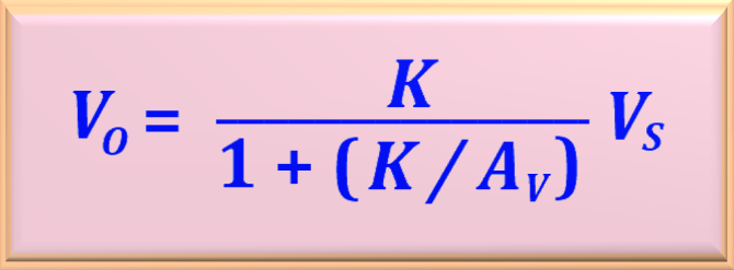
Thus, with this approximation we can rewrite the previous equation, arriving at:
Where K is the gain the closed loop, already seen and given by:
K = (Ri + Rf ) / Ri
Note that in the equation found for Vo, making
Av → ∞, the fraction is reduced to a value equal to
K . Exactly the voltage gain of an ideal amplifier
the closed mesh. So, the approximation made is very good when compared
to the ideal template. A good choice is to limit the gain value to the mesh
closed K, at least 1% of the value of Av.
Item b
The output impedance of an amplifier circuit is affected by the feedback. To analyze this situation, the
Thevenin equivalent is used for circuit output. The open circuit voltage and the short-circuit current must be calculated. The open circuit voltage, that is, Thévenin's voltage has already been calculated and will be repeated here.
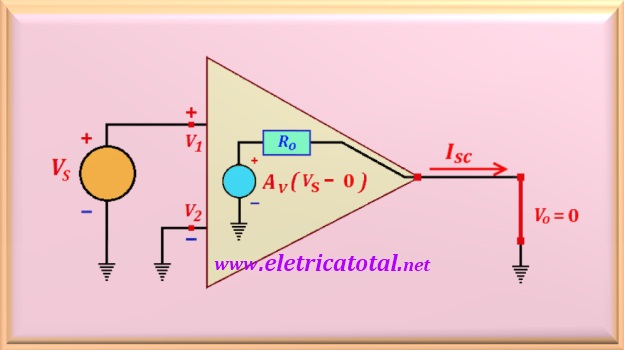
To calculate the short-circuit current, the output must be shorted and calculate the current through it. With the output short, obviously
V2 = 0 amd V1 = Vs.
See how the circuit was in the Figura 41-01.2.
Figura 41-01.2
Then, from the circuit, the current of short-circuit is:
Isc = (Av Vs ) / Ro
With this data we can calculate the Thevenin resistance, or:
Rth = Vth / Isc
Finally, making the necessary substitutions we find:
Rth = Ro [(K / Av)/ (1 +(K / Av))]
Note that for the case of K to be much smaller than Av
the equation can be simplified in such a way that the output impedance of the circuit is practically equal to zero. This can be easily understood by analyzing the simplified equation shown below.
Rth = (Ro K) / Av ≈ 0
For an operational amplifier like the LM 741, it is known that
Ro = 50 Ω and Av = 2 x 10⁵.
Using this opamp in a circuit where the closed loop gain is of the order of K = 100, the output impedance of the LM 741 will be in the order of
0.025 Ω. Practically zero.