Problem + Hard 14-1 Source:
Problem elaborated by the author of the site.
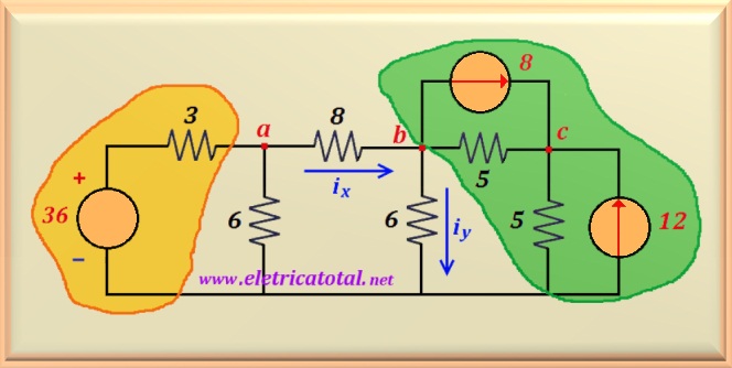
In the circuit shown in Figure 14-01.1:
a) Calculate the currents ix and iy
b) Calculate the power dissipated in the 6 ohms resistor.
Figure 14-01.1
Problem solving using Método da Transf. od Sourcesclick here!
Solution of the Problem + Hard 14-1 -
Superposição
Item a
This is a problem that to solve it by the superposition method it is necessary
of building three circuits, eliminating one source at a time. It stays like
task for anyone who wants to venture into an extensive resolution.
For this reason, it was decided to present its solution through the Circuit Method
Basic, method seen on the theory page. To remember, go to:
Basic Circuit Method
To do so, three font transformations must be performed simultaneously, as shown in the
Figure 14-01.2 in the regions highlighted in green and yellow.
Figure 14-01.2
In the circuit highlighted in yellow, it is noticed that the voltage source of 36 volts
can be transformed into
a current source of 12 A. And the 3 ohms resistor will be
in parallel with the 6 ohms resistor. Solving this parallel we find
a resulting resistor of 2 ohms.
On the other hand, in the circuit highlighted in green, the two current sources have been transformed
on two voltage sources.
Note that the two voltage sources will have opposite polarities. Soon,
their values must be subtracted and the positive pole must be facing the side
higher voltage source (in module). And the two resistors of 5 ohms each,
will be in series, totaling a single resistorof 10 ohms. One can
appreciate all these transformations in the Figure 14-01.3.
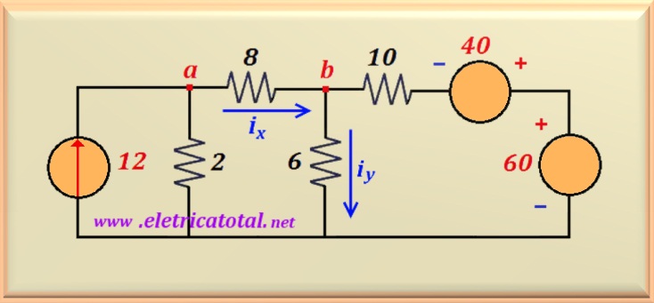
Figure 14-01.3
Thus, the circuit with the desired configuration is arrived at. Analyzing the circuit, one can write the equation that determines the voltage at node a, or:
Va = 2 (12 - ix)
Transforming the 12 A current source, which is
in parallel with the 2 ohms resistor, a voltage source is obtained
of 24 volts and, associating the two resistors that were in series, we obtain
a single one of 10 ohms. This is on the left side of the circuit. On the right side, it's just
subtract the source values resulting in a single voltage source of 20 volts
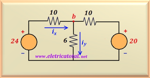
with the positive polarity facing up. See the Figure 14-01.4.
Figure 14-01.4
Based on the basic configuration studied in the MCB section in the "Basic Theory" tab,
We can identify the resistors as:
R1 = 10 Ω R2 = 6 Ω and R3 = 10 Ω
Thus, having identified the resistors, it is possible to calculate
the denominator of the equation represented by Rsp, which is given by:
Rsp = R1 R2 + R1 R3 + R2 R3
Replacing by the respective numerical values of the resistor that make up the circuit,
is found:
Rsp = 10 x 6 + 10 x 10 + 6 x 10 = 220
Now just find the numerator by cross-multiplying the sources
voltage of 24 and 20 volts, representing V1 and
V2, respectively, by the resistors R3 and
R1, or:
V1 R3 + V2 R1 = 24 x 10 + 20 x 10 = 440
And finally dividing this value by Rsp, we find the value of
iy.
iy = 440 / 220 = 2 A
Knowing the value of iy, to find eb it is enough
multiply by the value of R2 (Ohm's law) resulting in:
Vb = R2 iy = 2 x 6 = 12 volts
Knowing the value of Vb it is easy to calculate the value of ix,
then:
ix = (24 - Vb)/ R1 = (24 - 12)/ 10 = 1.2 A
With the calculation of this value we can calculate the voltage at node a. The equation is already
determined and we will repeat it here.
Va = 2 (12 - ix)
By substituting the variables for their numerical values,
is found:
Va = 2 (12 - 1.2) = 21.6 volts
From now on, just add and subtract "contains" obeying the
law of knots and Ohm's law.
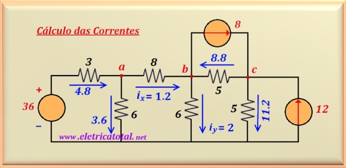
To conclude, the Figure 14-01.5 shows the complete circuit with all the indications
of the values of the currents flowing through the components of the circuit.
Figure 14-01.5
Item b
To complete the resolution of the problem, one must calculate the power dissipated in the
6 ohms resistor connected to node b:
Pb6 = 6 iy2 = 6 x 22 = 24 watts
To calculate the power dissipated in the 6 ohms resistor that is
connected to node a, the voltage Va = 21.6 volts is used, or: