


This chapter consists of the items below. If you want to go directly to an item,
1. - Introduction click here!
2. - Double Rotating Field Theory click here!
2.1 - Slip Calculation click here!
3. - Crossed Field Theory click here!
4. - Engine Equivalent Circuit Analysis Single-Phase Induction click here!
4.1 - Circuit Analysis with Engine Stopped click here!
4.2 - Circuit Analysis with Motor in Motion click here!
4.3 - Mathematical Analysis of the Engine Single-Phase Induction click here!
4.4 - Power in the Air Gap of a Single-Phase Motor click here!
4.5 - Calculation of Torque in a Single-Phase Motor click here!
4.6 - Rotor Copper Losses click here!
4.7 - Mechanical Power in Single-Phase Motor click here!
4.8 - Nominal Power of a Single-Phase Motor click here!
4.9 - Input or Electrical Power of a Single-Phase Induction Motor click here!
4.10 - Efficiency in a Single-Phase Motor click here!
4.11 - Study of Single-Phase Induction Motor no Load and with Locked Rotor click here!
4.11.1 - Single-Phase Induction Motor no Load click here!
4.11.2 - Single-Phase Induction Motor with Locked Rotor click here!
4.11.3 - Stator Resistance Measurement click here!
5. - Types of Single-Phase Induction Motors click here!
5.1 - Split Phase Windings click here!
5.2 - Motors with Starting Capacitor click here!
5.3 - Motors with Permanent Capacitor click here!
5.4 - Motors with Two Capacitors click here!
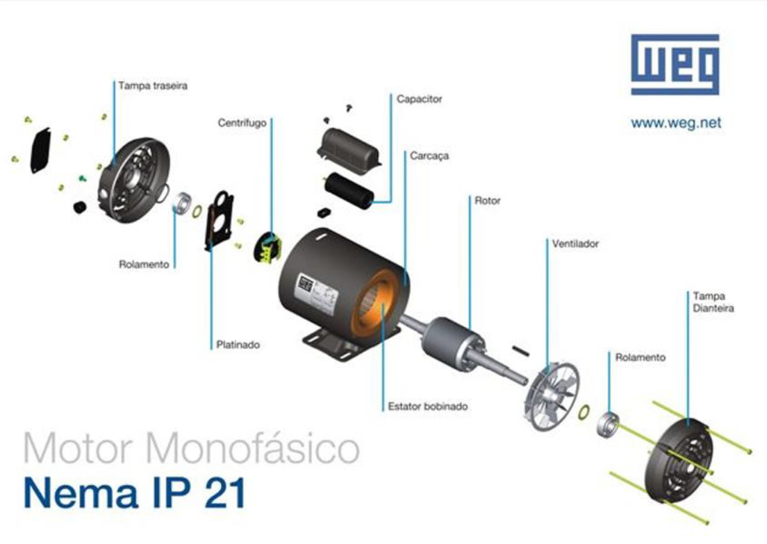
The biggest problem in the design of single-phase induction motors is that, unlike three-phase power sources, a single-phase source does not produce a magnetic field rotating. Instead, the magnetic field produced by a single-phase source remains stationary in the direction and pulses with time. Since there is no magnetic field rotating in the stator, a single-phase induction motor has no starting torque. Thus, conventional induction motors cannot work and the need for special projects arises.
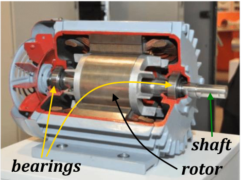
This can be easily seen by examining the engine when its rotor is
stopped. The machine's stator flux first increases and then decreases, but always
in the same direction. As the stator magnetic field does not rotate, there is no movement
relative between the stator field and the rotor bars. Therefore, no tension is
induced resulting from the relative movement of the rotor, no current circulates and consequently no
conjugate is induced. In reality, a voltage is induced in the
rotor bars by transformer action (
The history of the induction motor is marked by significant challenges and innovations.
At the end of the
In
There are two basic theories that explain why a conjugate is induced in the
rotor as soon as it starts to rotate. One is called the
2. Double Rotating Field Theory
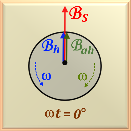


In this way, the decomposition of a pulsating magnetic field into two magnetic fields of the same
module rotating in opposite directions (progressive and retrograde fields) can be represented, mathematically, as a field
rotating clockwise and another counterclockwise. The field rotating clockwise, which we will represent by
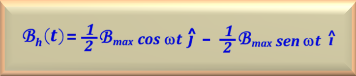
And the field rotating counterclockwise, which we will represent by
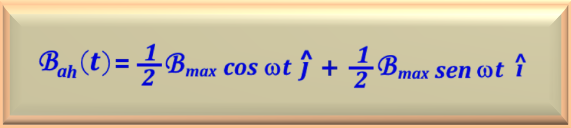
Note that the sum of the clockwise and counterclockwise magnetic fields is
equal to the stationary pulsating magnetic field

This analysis will be done based on
The forward and backward magnetic fields of the motor each contribute
a component of the total stator voltage and, in a certain sense, are in series with each other. Since both magnetic fields are present,
the rotating magnetic field
progressive rotor (which has a high effective rotor resistance
In addition to the average net conjugate, there are pulsations of
conjugate with twice the stator frequency. These torque pulsations occur when magnetic fields
progressive and retrograde intersect twice
each cycle. Thus, for a motor fed from a network whose frequency is

2.1 Slip Calculation
Assume that the motor rotor is rotating in the direction of the field, which in turn rotates progressively (counterclockwise) at a
speed

Now suppose that the engine rotor rotates in a counterclockwise direction.
Then, the slip

Therefore, algebraically developing the above equation, the slip
3. Crossed Field Theory
It is a theory between the voltages and currents that the stator's stationary magnetic field can induce in the stator's bars rotor when it is in motion.
Consider a single-phase induction motor with a rotor that has been brought to the
operating speed through some external method. Voltages are induced in the bars of this rotor, with the voltage
peak occurring in windings that pass directly below the windings
of the stator. In turn, these voltages produce a current flow in the rotor which,
Due to its high reactance, it lags behind the voltage by almost
The rotor magnetic field is smaller than the stator magnetic field
due to losses in the rotor, but they differ from each other by approximately
If the engine rotor had initially been turned clockwise, then the resulting torque would be clockwise and again keep the rotor turning.
4. Engine Equivalent Circuit Analysis
Single-Phase InductionThe double rotating field theory is fundamental to understanding the operation of single-phase induction motors. When the stator is powered by a single-phase source, it actually creates two rotating magnetic waves of equal magnitude, but which rotate in opposite directions. These waves are crucial because one of them interacts with the rotor to produce the torque necessary for engine operation.The other wave, rotating in the opposite direction, does not contribute to torque and can even harm engine efficiency. Therefore, engineers and engine designers look for ways to minimize the effects of this contrary wave to improve engine performance. The analysis of this theory allows a more accurate assessment of the engine's starting and operating characteristics, as well as its efficiency and power factor.
4.1 Circuit Analysis with Engine Stopped
The best way to start analyzing a single-phase induction motor is
examining the engine when it is

In this model the variables involved are:
It is interesting to highlight that the voltage

Analyzing the behavior of electric motors when stopped is essential for understanding how they work
and for carrying out accurate diagnoses. In the case of a stopped motor, the pulsating magnetic flux in the air gap can,
in fact, be divided into two rotating fields of equal magnitude but in opposite directions. This division results in two
components that interact with the rotor circuit, causing both resistive and reactive voltage drops.
Understanding this interaction is crucial, as it allows the rotor equivalent circuit to be divided into two parts.
that reflect the effects of each magnetic field. This division is a direct application of rotating field theory,
which is a pillar in the analysis of electrical machines, especially those that operate with alternating current.
Furthermore, the air gap concept is essential for engine design and analysis, as it is the space where engine
magnetic interaction between the stator and rotor, being a critical factor for the efficiency of the motor.
It is possible to divide the rotor equivalent circuit into two sections, each
corresponding to the effects of one of the magnetic fields. The equivalent circuit of the
motor, including separation of effects due to progressive magnetic fields
and retrograde is shown in
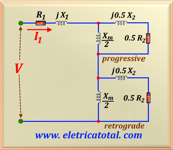
In this way, the two halves, in the stationary rotor condition,
have the same
4.2 Circuit Analysis with Motor in Motion
The effective rotor resistance in an induction motor is a crucial factor that influences the motor's performance, especially in relation to the relative movement between the rotor and stator magnetic fields. The progressive magnetic field, which rotates in the same direction as the rotor rotation, and the retrograde magnetic field, which rotates in the opposite direction, contribute in a different for the rotor resistance. When the motor is running, the effective resistance of the rotor to the field progressive field is different from that for the retrograde field due to the slip variation, which is the difference between the speed of the rotating magnetic field and the actual speed of the rotor. This phenomenon is fundamental to understanding the dynamic behavior of induction motors and for the development of speed and torque control methods more efficient.
For the
The
See the final equivalent circuit of the moving single-phase induction motor in

4.3 Mathematical Analysis of the Engine
Single-Phase InductionPower and torque relationships in electric motors are fundamental to understanding the performance and efficiency of these machines.
In single-phase motors, these relationships are also applicable, considering the progressive and retrograde components of the magnetic field.
The net power of a single-phase motor is the difference between the powers associated with each of these fields, while the torque
net is the difference between the conjugates they produce. This principle is essential for engine design and analysis
single-phase. In

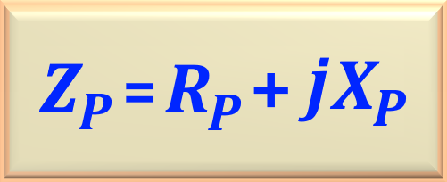
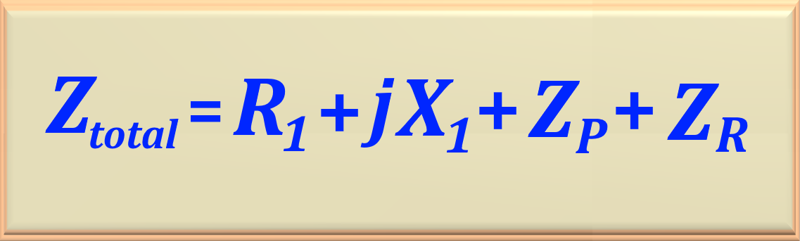
To make the calculation of the motor input current simpler, it is customary to
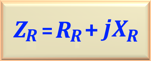
define the impedances
This way, simply by looking at the circuit shown in


Note carefully that after the numerical calculation of the values of
In

To complete this analysis, using

These equations are valid for the
"Note that when using these equations there is no need to work with
4.4 Power in the Air Gap of a Single-Phase Motor
After understanding the theoretical part involved in a
Let's start by determining the motor input current, represented by

Note that the denominator of
It is important to note that the progressive air gap power of a single-phase induction motor is the power
consumed by

This equation represents the value of the power developed by the rotor to produce a torque necessary to maintain the rotor rotation.
This difference between the quantities
And the progressive power in the air gap is given by:

And the retrograde power in the air gap is given by:

Replacing the respective values in

"
4.5 Calculation of Torque in a Single-Phase Motor
When we studied the three-phase induction motor we saw that the torque induced in the rotor was given by

Note that we use the

Since the two fields, progressive and retrograde, are rotating in

Using

All these equations make it possible to calculate the

To calculate
4.6 Rotor Copper Losses
The

Losses due to the retrograde field are given by:

Therefore, the rotor copper losses are given by adding the losses due to the forward and backward field. Then, the losses are:

Here it is

4.7 Mechanical Power in Single-Phase Motor
After deducting the losses inherent to the operation of the engine,
such as copper losses due to electrical resistance, ventilation and friction losses, and supplementary and core losses,
mechanical power represents the energy effectively available to perform work, that is, that
power that can be converted from electrical to mechanical form. This power, known as

Thus, making the necessary equivalences we can write the

Substituting

Substituting

And, based on

Simplifying the above expression further, we can also write that

Note that depending on the data provided in the problem statement, we have several alternatives to calculate the
4.8 Nominal Power of a Single-Phase Motor

4.9 Input or Electrical Power of a Single-Phase
Induction MotorNote that the electrical power (measured in

In this equation,
We must also be aware that the machine's input power must satisfy

4.10 Efficiency in a Single-Phase Motor
The efficiency,

4.11 Study of Single-Phase Induction Motor no
Load and with Locked RotorWhen a motor operates at no load, that is, without load, it consumes a minimum electrical current necessary to overcome the internal losses, such as iron losses and friction and ventilation losses. The empty condition is important to determine engine behavior in situations close to ideal operation. During a no-load test, the rated voltage is applied and the electric current is measured by an ammeter connected in series with the motor, as well as the real power consumed, which is indicated by the wattmeter. These measurements allow calculate motor rotational losses, which are crucial for understanding motor efficiency and for designing systems that use electric motors more effectively and economically. Therefore, this test is a valuable tool in electrical engineering to evaluate the performance of motors under controlled conditions.
Due to the high reluctance in the air gap of an induction motor, the current circulating through the winding
of the stator is very high. Thus, the
Therefore, when the engine is running without load, there are two relevant simplifications to be made. The first
is in the case of the progressive rotating field, where the portion

The second simplification is in the case of the retrograde rotating field, where the portion

This allows us to assemble the equivalent circuit for the case of the engine operating

It is observed that a resistance called
The current in the rotor due to the progressive flux is very small, so copper losses are neglected.
However, the current due to retrograde flow is significant, and the corresponding copper losses are represented by

In the same way as we did for the

And, after defining the

And finally, the power read by the wattmeter will be represented by

Remembering that

We must note that since the motor has a blocked rotor and, therefore,

It can be seen that we can calculate the

Another information that can be removed from the circuit is the electric current,

Where the value of

Now, knowing the value of

It is important to solve many problems the relationship between the

Another important fact that we must highlight
is that this method finds the total resistance value, that is,
It is worth noting that, in general, it is a consensus to establish a relationship between
Another widely used method to determine the electrical resistance of the motor magnetization winding, in this case
It is also known
that the reactance of the motor is

5. Types of Single-Phase Induction Motors
All of these starting techniques are methods in which one of the motor's two rotating magnetic fields is made stronger than the other. In this way, the rotor receives a starting torque in a certain direction.
We will study each type of engine separately.
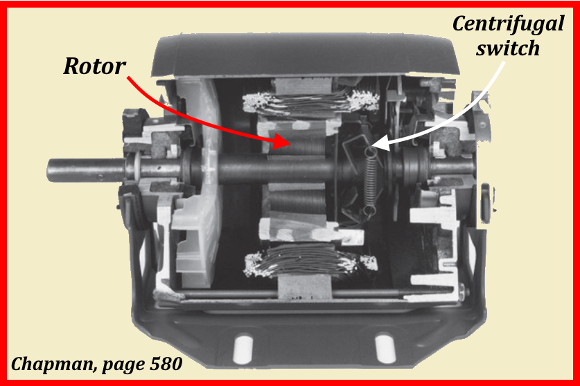
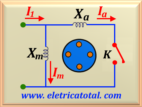
5.1 Split Phase Windings
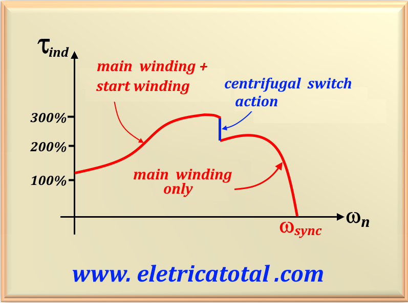
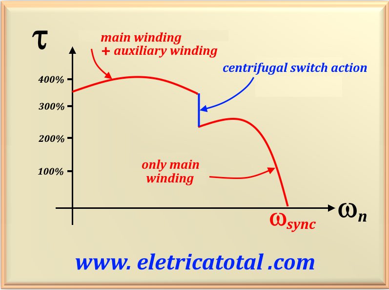
The split phase motor is a classic type of induction motor, widely used in applications that do not require a high starting torque. The 90° phase shift between the stator windings is essential to create a magnetic field rotary, which is what allows the engine to operate. The main winding is responsible for continuous operation, while the auxiliary winding, in conjunction with the centrifugal switch, is used only during starting to help overcome the initial moment of inertia. The centrifugal switch is connected in series with the auxiliary winding. The split phase motor is a classic type of induction motor, widely used in applications that do not require a high starting torque. The 90° phase shift between the stator windings is essential to create a magnetic field rotating, allowing the engine to operate. The main winding is responsible for continuous operation, while the auxiliary winding, in conjunction with the centrifugal switch, is used only during starting to help overcome the initial moment of inertia. The centrifugal switch is connected in series with the auxiliary winding.
An important fact in this type of motor is to design an

Split-phase motors have a moderate starting torque with a low starting current. Starting torque can be increased
inserting a resistance in
They are used in applications that do not require very high starting torques, such as fans, blowers and centrifugal pumps. They are available in sizes in the fractional power range and are very inexpensive.
"The direction of rotation of the motor depends on the
spatial angle of the auxiliary winding magnetic field is
5.2 Motors with Starting Capacitor
The use of a starting capacitor in electric motors is a common practice to improve starting torque, especially in single-phase motors. The capacitor, when connected in series with the auxiliary winding, creates a phase shift between the currents flowing through the motor coils. This results in a field additional rotating magnet that helps the motor start its rotation. The ability to adjust the strength magnetomotive starting current of the auxiliary winding so that it is equal to that of the main winding is crucial as it allows for a more efficient and smooth start. This method is particularly useful in applications that require robust starting torque, such as fans, pumps and some household appliances. However, i t is important to note that the capacitor must be sized correctly for the specific application in order to prevent premature failures and ensure engine operational efficiency.
See
Typical applications of these motors are in compressors, pumps, air conditioning and other types of equipment whose starts occur with load.
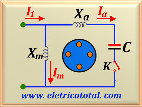
In
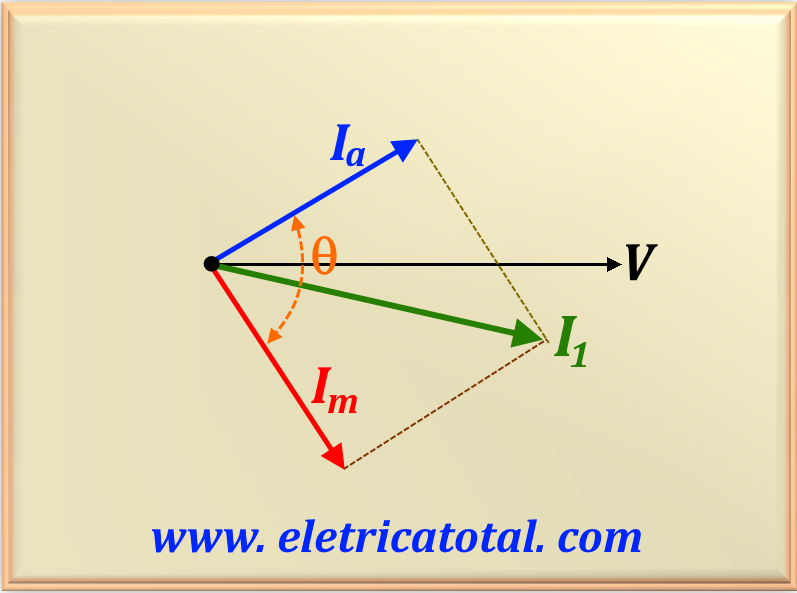
To find an equation that defines the
Let's define the variable

It is common, in technical literature, to define a new variable by the letter

So, the equation

In
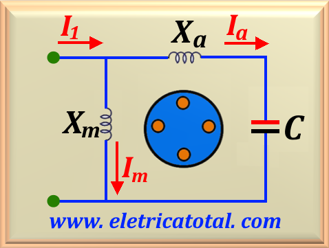
5.3 Motors with Permanent Capacitor
The starting capacitor does such a good job of improving the torque characteristic versus
speed of an induction motor that sometimes the winding
auxiliary with a smaller capacitor is left permanently in the motor circuit.
If the capacitor value is chosen correctly, this motor will have a perfectly rotating magnetic field
uniform for some specific load and it will behave
exactly like a three-phase induction motor at that point. This motor is called a
However, permanent capacitor motors have a starting torque
lower than capacitor-start motors because the capacitor must be
dimensioned with a certain value to be able to balance the winding currents
permanent and auxiliary load under normal load conditions. How does the starting current
is much greater than the normal charging current, a capacitor that balances the phases with
normal loads will leave these phases very unbalanced under operating conditions
match. In
Note that in this configuration the relationship shown in


5.4 Motors with Two Capacitors
Dual capacitor motors are an effective solution for applications that require high starting torque.
The use of two capacitors, one for starting and one for continuous operation, allows the motor to develop
stronger starting torque and improve efficiency during regular operation. The starting capacitor, with value
higher, is crucial during the first moments after activation, as it works to balance the currents
between the main and auxiliary windings, resulting in a higher starting torque. Once the engine reaches
its rated speed, the centrifugal switch system deactivates the starting capacitor, leaving only the starting capacitor
permanently in operation. The latter, being of lower value, generally between

